"Big Foot 49"
or
Electric ...
The way how dramatically I miss-guessed
the required time for the work on electric was tremendous. Here just one
example for the new automatic cut-out:
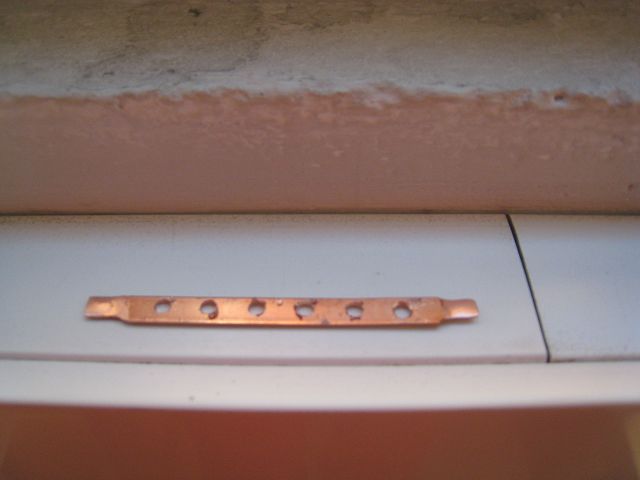
First of all I needed a copper-stripes to
power 6 of the automatic cut-outs simoultaniously -
as long as required like that . To do so I bought cupper connectors for
automatic cut-outs of house installations.
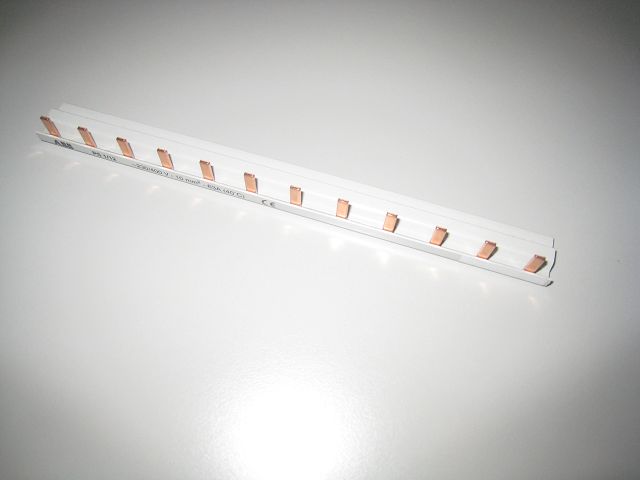
The plastic isolation was removed and the
hooks cut off.
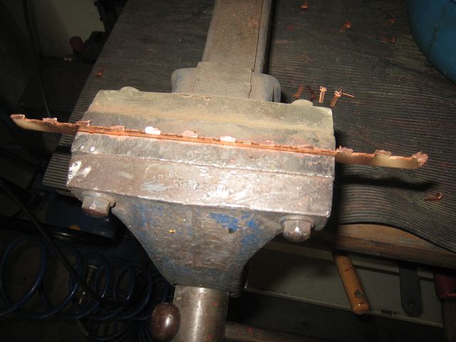
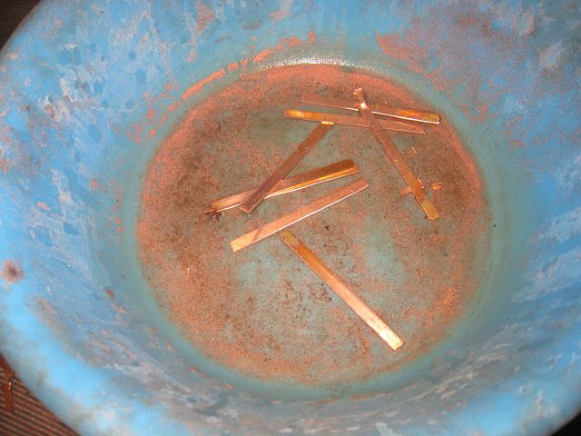
Afterwards the sharp edges were removed
and the pieces reduced to the required length. Due to the heat of the cutting,
polishing etc. the parts needed to be cooled down again in water.
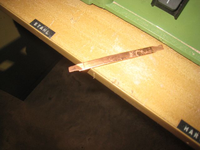
Both edges were made smaller and thinner
plus a short use of the drilling machine (not done so far on this particular
strip) so that flat connectors (typically used in car industry, 6,3 mm) could be
pushed on and wan't fell off again.
Afterwards I drilled holes to connect the
stripes with the automatic cut-outs with screws - of course the drills were
deburred finally. 
After the raisers had been made out of
hardwood ...
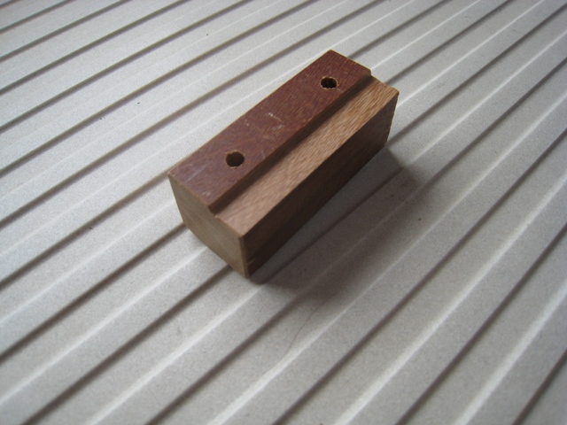
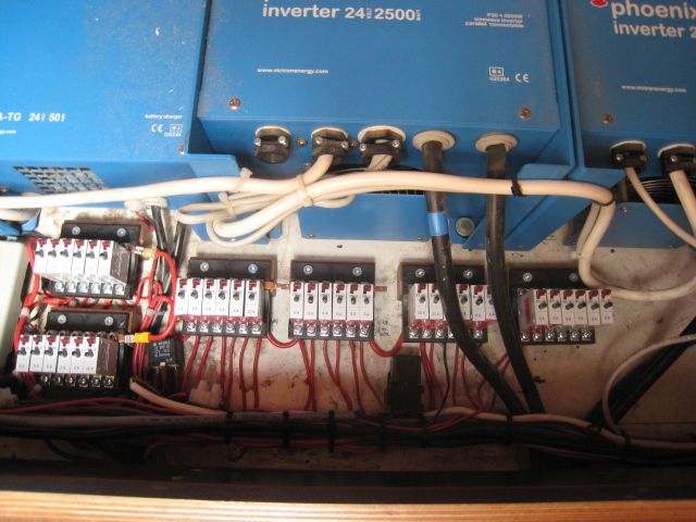
... and the automatic cut-outs had been
mounted on the plastic holders with screws, then together with the wooden
raisers had been screwed to the ground and finally all had been wired it finally
looked like that:
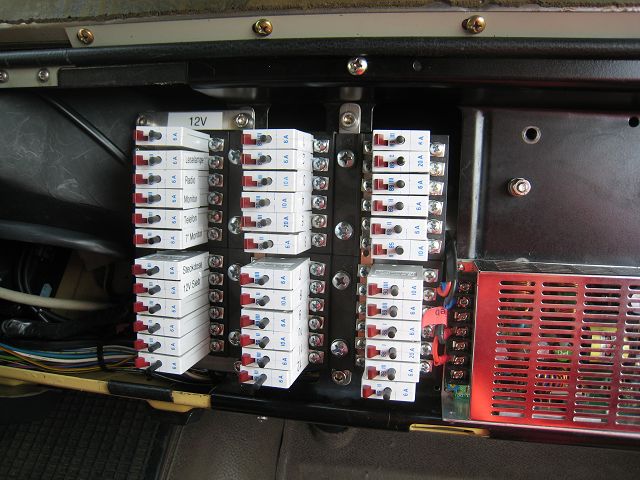
The normal fuses in the drivers cabine
were removed as well. Here I only needed a metal stripe to combine two plastic
holders together, the multi-cable-connectors fitted perfectly. And the depth to
the rear and top was as well more than sufficient - so against my original
worries even easierthan the exchange of the fuses in the cabine.
The automatic cut-outs I have bought from Thomas
Hirschberg, he still has more to sell ,
WHO IS
INTERESTED PLEASES CLICK HERE or here for his
private website.
A really nice guy gave me some of these
muliple sockets with a securing hook which prevents that the plug can fall off
accidently - thanks again very much Karl-Heinz (he knows whom I am talking about)!
(It is obsolete to mention that so far never a conventional plug
fall off, but now it is PERFECT!) 
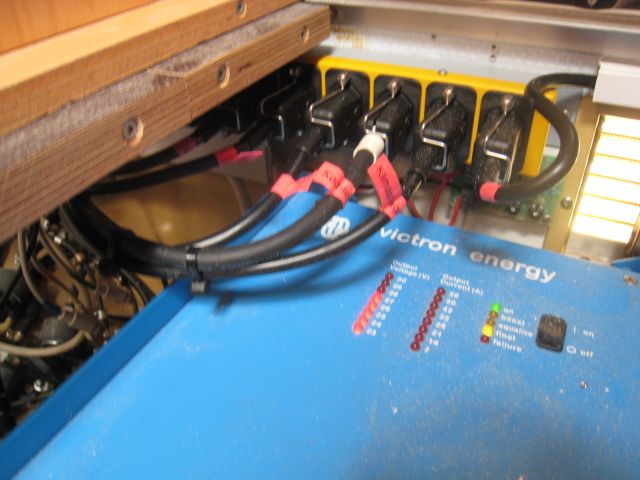
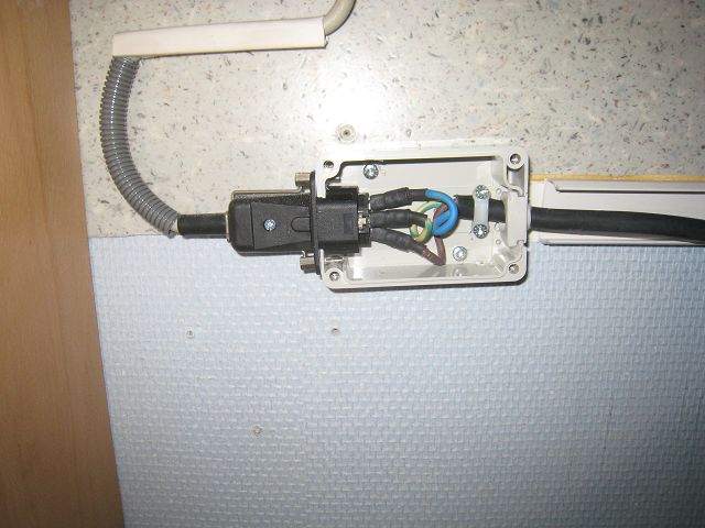
And because I had several of these
multiple sockets it was OK to "canibalize" one for single use, here e. g. to
connect the cooking plate. So I integrated one of these sockets into a small -
here without the cover.
Yeah, ther rear part of the switch-board
was since a long time something which I didn't like.
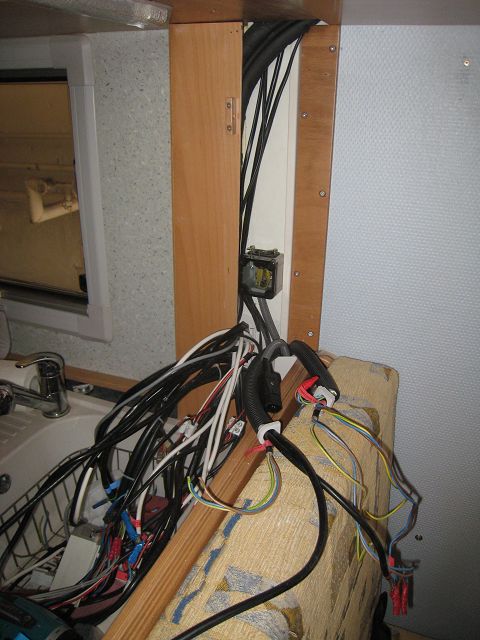
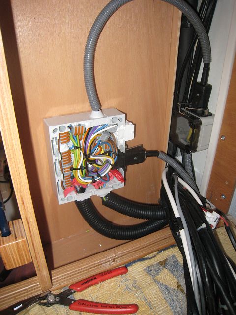
So first of all I separated the 230V-installation
completely from the 12V- and 24V-system. The patching is installed in a separate
box.
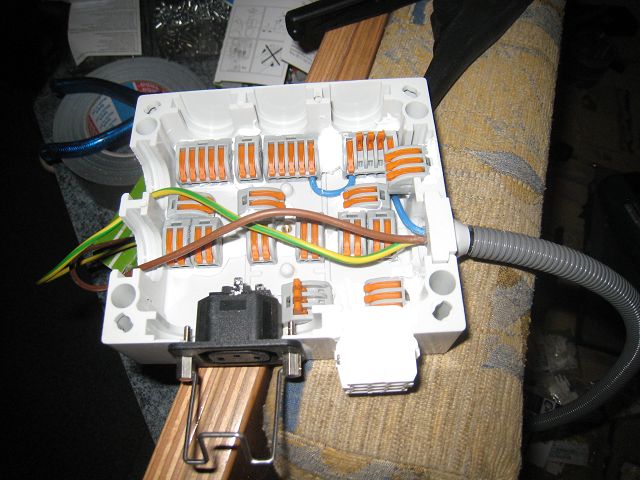
Thats how it looks when I had finisched
the wiring and applied protection tubes.
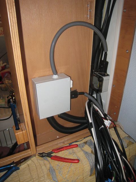
And here with cover!
The 12V & 24V-installation was
combined on several plugs and sockets for flat connectors 6,3 mm.
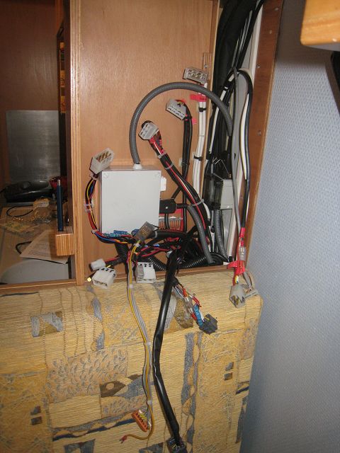
Because of the huge amount of wires I had
to use ~15 plugs and sockets which I didn't ike in case of service - too many to
dis- and re-connect, even if it is a service board which I will open only very
rarely and only in case of service or when I want to add anything!! 

So finally I changed everything again and
have refitted everything on a special 9-pin socket for 230V, 1x 16-pin-socket, 1x 16-pin
plug, 1x 37-pin socket plus one remaining 6-pole socket for 6,3 mm flat
connectors (no other choice because of the 2,5mm² cables for switching on / off
the water pumps).
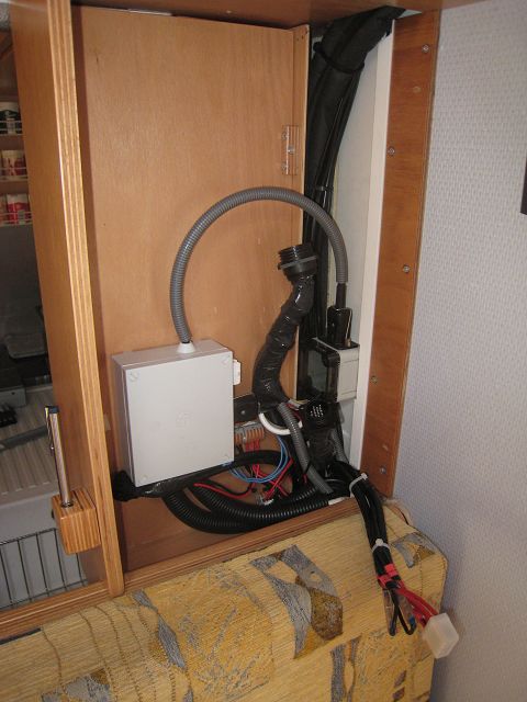
Thanks to Mark for organizing the
special-coloured and fine-wired cables!
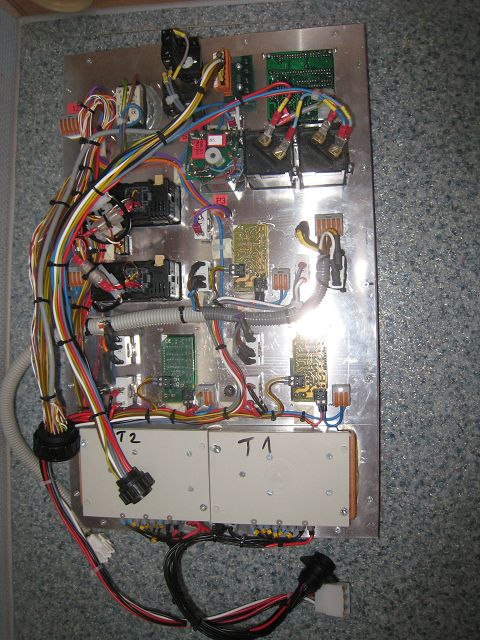
The rear side of the switch board:
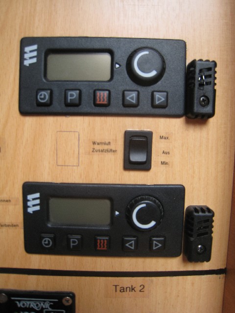
The Eberspächer airheating didn't work as
expected and so I had to apply an additional temperature sensor. Without these
sensors the fan is permantly on so that the sensor integrated in the air heating
can recognize more or less accurate the temperature of the room. The sensors
were integrated for boht air heatings.
Last but not least I have finished the
installation for the 24V generator:
 | As soon as I engage a switch on switch
board a pneumatic valve opens by two pneumatic cylinders the covers to the
housing of the generator (pls. have a look as well
here). |
 | Simultaniously the vans start to work (two
push cool air in, two pull out the hot air). |
 | A magnetic valve opens the diesel
supply. |
This was the status so far.
The remaining problem was the exhaust. The exhaust of the generator is next to
the "in"-cover and the first idea to push out with a third van the exhausts
would have failed sooner or later because the dust and dirt of the exhausts
would have damaged the van quite quickly.
So I built an electric waste water valve in front of the exhaust. So I was able
to operate without an additional van because it is now a straight flow of the
exhausts.
The electric valve needs ~ 5 sec. power to run open and the same time but
reversed connection of "+" & "-" to close.
This would have required an additional switch in the control board (which would
have 1. ment to use an additional wire was and 2. I wouldn't have liked long
time because I prefer simple handling - even if this means that the workload to
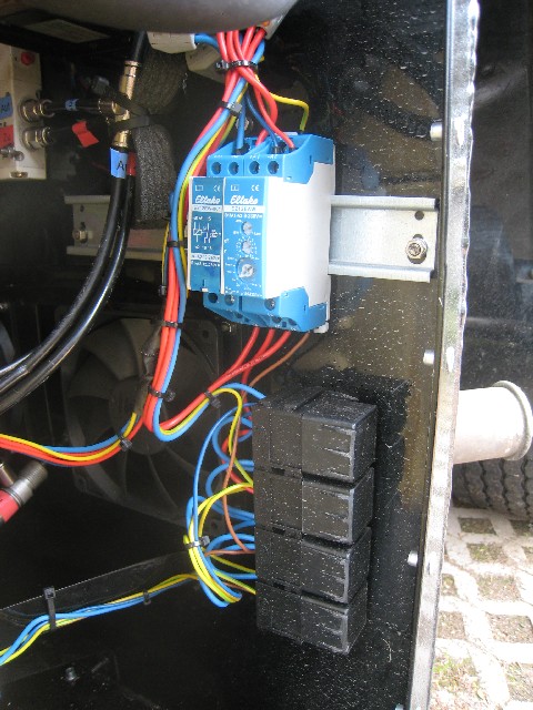
achieve that goes into extrems) and so I built in two special relays. The first
gives once I have switched the above to "on" for 5 sec. power (passing
make-contact). The second
switches for 5 sec. to "on" once the above switch is turned to "off"
(passing break-contact). Both 5
sec. power impulses go to 4 more relays to change the polarity (the first two to
give "+" and "-" to the valve to open, the next two to give "-" and "+" to the
valve to close).
Thanks as well to
Mr. Streubel from company Streubel
Automation resepctively Pneumatikwelt.de for his quick, friendly and
friendly support to me and this project. He is my supplier for the pneumatic
cylinders etc..
Definitely NO thanks to
Conrad respectively their bullsh...
forwarding agent Hermes, who delayed the shipment of elektric parts to 1 WEEK!!
Note: The last shipments arrived well in time due to Deutsche Post - much better
now!
The final test will be next Thursday when
I will join the ralley "Dresden-Breslau" - another update to follow.

 Besucher/Visitors